Having made the decision to build my own backyard train using plans from 1965 issue of Popular Mechanics magazine, my first research project was to determine where to put the track for the train to run on. The plans call for a minimum radius of thirty feet for the curves (a tighter radius would tend to make the train derail), so I had to have at least sixty feet between the two sides of the oval (assuming a simple track pattern of two 180 degree turns with a straight run between them).
I finally settled on a location that would take the track bed through some wooded area for half the run (dodging the larger trees that I don’t want to clear), and in a clear area for the remainder. But the track area is not level, so the train will have to be able to pull a grade. By measuring the vertical drop from the high side to the low side, and calculating the linear run of the track, I figured that the grade will be about 3.8%. This is pretty steep for a train, so I don’t know if the engine will be able to climb a grade this steep.
The only way to know for sure is to build the engine, lay some track, and run some tests. If the engine can handle it, then I’ll just lay the track on the ground. If not, then I’ll have to figure something out. I could reduce the grade by trenching the high side, or by elevating the track on the low side with trestles. But I’ll deal with that problem later, if I have to.
So, at this point, my goal is to get the engine chassis far enough along that I can run some hill tests before I can start building the track. But to get a running chassis will require the completion of the engine frame, wheels, axles, and bearings, drive motors and drive train, and some sort of remote control device so I can stop it before it runs off the end of the track.
By the way, this project brings entirely new meanings to common phrases in my lexicon, such as “train wreck”, “off the rails”, “light at the end of the tunnel”, and “add the bells and whistles”.
I’ve made a list of materials and supplies that I know I’ll need to get started, and have purchased the ones I know I need to start building the chassis of the engine. The plans call for plywood in thicknesses of 3/4″ and 3/8″. Neither Home Depot or Lowes carry sheets of 3/8″ plywood. But I’m using 1/2″ in its place. I don’t know how that will affect the measurements of some of the pieces yet.
I’ve got most of the pieces cut on the band saw and set aside for later. Now that the chassis is cut out, I need to get the wheels and axles built and installed so I can run the “hill climb” tests. That’s next.
The plans show that the wheels comprise a V-pulley (with one of the flanges removed) sandwiched against two or three layers of plywood cut in the shape of the wheel. The sandwich is held together with bolts that go through the plywood pieces and a hole in the V-pulley spokes.
My V-Pulley has perpendicular reinforcing ribs along the spokes; drilling a hole through the spokes would weaken the spokes. So I need to modify the plans to preserve the structural integrity of the pulleys.
Pieces for the pilot wheels
My solution is to cut wedge-shaped pieces that I can fit between the spokes on the back side, and have the bolts go through the wedges on one side and the wheel plywood on the other. There also are some other design alterations I had to make to accommodate my pulleys. But I think they will work out Ok.
The plans also call for a “live” axle for the drive wheels. By “live” axle, I’m referring to one axle that’s attached to both drive wheels so that both drive wheels turn together. This would be a simpler solution, as I could have just one gear sprocket on the axle and have it turn both wheels. This is the way the real steam engines are built.
One of the problems with this approach is that, when the engine goes around a curve, the outer wheel spins a little bit faster than the inner wheel. If both wheels are fixed to the axle, then one of the wheels will have to slip on the track. This will cause the outer wheel to have a tendency to try to climb the rail and derail the engine.
Pieces for the drive wheels
My solution is to take advantage of the computer controller I’m going to build and have the computer turn the outer wheel faster than the inner wheel. If I can do the arithmetic correctly, then I should be able to program the motor controller to make the wheels turn so that that is no slippage. I’m also thinking that another advantage to this approach might be that, if I can turn the outer wheel faster than the inner wheel on a curve, then in theory I might be able to have a track curve with an even smaller radius. Turning the outer wheel faster should force the engine to try to turn with the curvature of the track.
So I’ll need to build the wheels and axles so that all six wheels can spin freely on the axle, and add a drive sprocket to each of the rear wheels.
Click on each image to get a description of its construction:
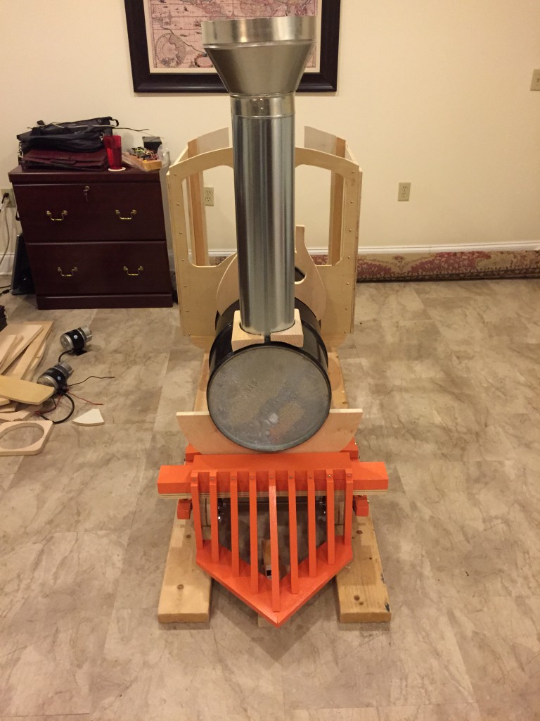
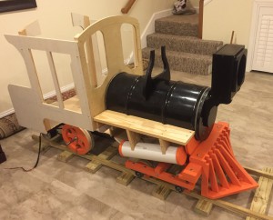
Now that I have the chassis and wheel assemblies in place, I can put a few of the other pieces together to start to get a sense of what the engine might look like.
Since I’ve cut out most of the pieces, I took some 1 1/4″ sheet metal screws to temporarily tack the pieces of the cab together so I can set it on the chassis. I’ll eventually replace all of the screws with stainless steel truss head screws, but that’s for later. The truss head screw has a broader head for the screw size, and will more closely resemble the steel boiler rivets that were used in the steam engines.
I’ve also set the sixteen gallon steel drum on the chassis to help with the overall effect. Here’s the upshot:
Chassis with Partial Cab and Boiler
I’ve also built the cow-catcher (twice). Lots of odd angles and lengths to get right. Here’s some photos with the cow-catcher sitting on the front of the engine. Also note the smoke stack. The stack is a piece of six inch duct in a two foot length from Lowes, along with a duct reducer I bought online. I’ll have the shorten the smokestack and figure out how to attach the stack to the drum with a clean look:
I don’t have any plans or guidelines for the motor controller, so I’m on my own. Here’s the issue: the two 350W DC motors will be powered by a pair of twelve volt wheelchair batteries wired in series, which will provide twenty-four volts of power. If the power is controlled by an on-off switch, then turning the power on would provide the full flow of current instantaneously. The motors would go from zero to full speed immediately, causing the engine to jerk as it attempts to go immediately from zero to full speed.
In addition, there would be no provisions for speed control. With this configuration, it’s either no power or full power, with no intermediate speeds.
To provide for a gradual and smooth ramp-up of power and speed, we need some way to make the motors run at a variable speed, sort of like a variable speed drill. In researching this problem on the World Wide Web (i.e., “Google”), I’ve learned quite a bit about how to make this happen. While there are several approaches, the consensus approach is to use an H-Bridge and a digital controller.
The H-Bridge is a device that uses Pulse Width Modulation (PWM) to control a motor. Think of a stream of current flowing at twenty-four volts. Now divide that stream into pulses so that there are thousands of pulses each second. For each micro-pulse, imagine that you can somehow modulate the pulse so that the voltage flows for just a percentage of the pulse. For example, at 20% there would be voltage flowing for 20% of the pulse, and no voltage flowing for the remaining 80%. The high frequency of the pulses would have a smoothing effect, such that when the motor sees the current, it only sees a smooth flow of 20% of the power flowing. So the twenty-four volts would look like 4.8V to the motor. That’s essentially what the H-Bridge does.
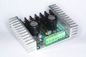
Sabertooth Dual Motor Controller
After some more research and reviews, I selected for the H-Bridge a component called Sabertooth sold by DimensionEngineering.com. This device lets you hook the battery wired into its terminals, and the motor leads into other terminals. It also lets you wire a signal wire into it to control the voltage. So to run the motors at 10% capacity, you can provide the signal wire the appropriate value and it routes 10% of the incoming power to the motors.
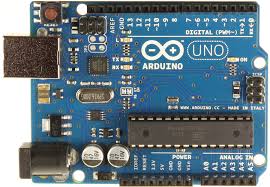
The next question is how to provide the signal. I’m using a programmable microcontroller board called the Arduino Uno. This board allows you to develop your own computer program that you can download to the board. It also allows you to (among other things) attach various sensors that it can monitor and respond to. So you can attach a potentiometer, for example, that you can use as a throttle. The potentiometer allows you to dial in a variable speed value that the board can sense. Think of the volume control knob on an old radio. The more you turn it, the louder the volume.
Arduino
By sending the adjusted values of the potentiometer to the controller board, the board can then determine what speed the motors should be running and send the appropriate signal to the Sabertooth board. That’s basically how my motor control circuit will work.
By developing my own computer control software, I can have it make one wheel turn faster in a curve than the other. The custom control circuitry opens up a number of other possibilities for enhancements down the road (track?), including adding a sound module and speaker to make steam engine sounds or train whistle sounds, control lights, or other things I haven’t even thought of yet.
Flysky
It also lets me integrate a Radio Control (RC) capability. I’d like to be able to control the train either with an on-board speed control or with an RC transmitter so I can control it remotely for testing and maintenance. When small children are on board, it also will let me take control remotely if they’re about to get into trouble. I’m using the FlySky FS-CT6B RC controller.
Here’s my first microcontrol circuit board:
Circuit Controller
The unit on the right with the cooling fins is the Sabertooth motor controller. The middle unit is a PCB board with a potentiometer soldered in to set the speed, and the unit on the right is the Arduino programmable microcontroller. The little black thing on the bottom is a RC receiver that listens for the Radio Controller commands. The rat’s nest of wires ties it all together. I’m hoping that Homeland Security doesn’t take an interest in this!
Update:
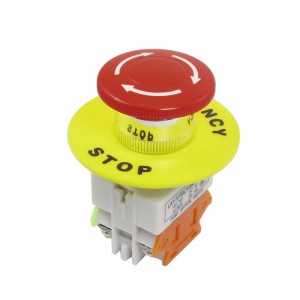
Eventually I’ll need to figure out where on the engine to mount the batteries and electronics and get the wiring in place. For now, it occurs to me that I’ll need some sort of Kill Switch as a safety device. If something goes wrong that I didn’t foresee, there needs to be a big red STOP button that the operator can slap to shut the whole thing down. It can also double as a power disconnect to prevent any possible battery drain.
Update on the Update:
Emergency Stop button on Amazon.com. Sorta reminds me of Hillary’s Reset button she presented to the Russian Foreign Minister Lavrov. Let’s hope mine works better than hers did.
I’ve looked into the big red STOP button. The proper term is “E-Stop” (for Emergency Stop). All of the buttons I’ve found on the World Wide Web (at least that are affordable) are rated at ten amps. Since I’m going to run twenty-four volts into a pair of 350W motors, I’ll potentially be drawing around twenty-nine amps of power. So it’s probably not a good idea to route all this power through a ten amp button.
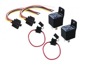
The alternative is to do what they do in automobiles for horns and lights that draw more power than a typical switch can accommodate: build a relay circuit.
Automotive relay and fuse on Amazon.com
I can get an automotive relay rated at thirty or forty amps and have the ten amp E-Stop button control the relay. The relay can control the circuit that handles the higher load. It’s a little more complexity than I was hoping for, but it is what it is.
While I was thinking about this problem it also occurred to me that I probably need to put some sort of line fuse in while I’m building the circuit. Again, if something unforeseen goes wrong, I’d rather burn out a one dollar fuse than a hundred-plus dollar control circuit.
The plans include a box for the headlight that’s mounted on the front of the boiler. This 1965 version has a light consisting of a candle sitting in the wood box with a round reflector mirror behind it. This seems like an insane fire hazard, plus we have better technology available to us today.
I’m thinking I can get an LED lantern for under ten bucks and strip out some parts to use as a light. It’s a bright light, and uses very little energy. I’m not sure about how to power it, though. Most of the lanterns are designed for a six volt battery; I’ll be powering the train with twenty-four volts. I’ll have to check the ratings on whatever LED light I find to see if I can run it on twenty-four volts without frying something. If not, then maybe I’ll just add a separate six volt battery in the light box for its own power source. It looks like there should be room in the box for the battery as well.
In either case, I should be able to control the light through my computer controller. Again, I’ll figure that out later. For now, I just want to get the light box built.
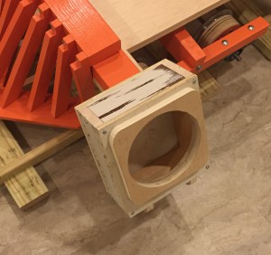
Box for headlight
Here’s the box. I used some scrap wood that had previously been used to experiment with various paint techniques for getting that distressed look for an unrelated project. It won’t matter, as the box eventually will be painted black.
I also haven’t sanded it yet. So the final version should look smoother.
Mounting feet too close together
After getting the box built, I checked to see how it will mount to the front boiler plate. The two mounting feet are too close together. You can see from the plans that the feet should straddle the little medallion that goes in the center of the front boiler. I’ll have to reposition the feet on the box before I can mount it.
Update:
Here are some pictures of the headlight box mounted to the front of the boiler. Click on each picture for more information:
Next steps: Installation of the wiring and control circuits!
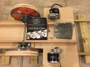
The objective up to this point is to get enough of the engine and track built that I can run some hill-climbing tests. The results of these tests will determine how I build the track. Now that the running gear (axles and wheels) are in place, it’s time to install the motors and drive chains, and then to wire it up to see if it runs.
Here’s a look at where the motors will mount on the underside of the chassis. The first drive chain I purchased was too wide to fit within the tight clearances required. This is the replacement chain that’s more narrow in width. There are several different sizes of roller chain that vary in pitch and width; mine was determined by the size of the sprockets on the motors I purchased. I had to find drive sprockets to match.
Chassis Underside
This is a look at the underside of the chassis (with everything removed for painting). Note the stiffening ribs on the right; also note the eight slotted holes for mounting the motors. Mounting the motors here will make the visible on the underside of the carriage when the train is running, but there’s nowhere else to put them without interfering with either cab space or the brake and throttle linkages.
Update
I’ve reassembled the underside of the chassis, including all of the running gear (wheels, axles, motors, and drive chains). Next step is to figure out where and how to install the batteries and electronics.
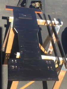
Engine with steam cylinders and boiler attached
There’s lots of room inside the boiler (steel drum). But I’d have to cut holes in the steel to pass the wires. I’d rather keep the drum intact as much as I can to prevent flexing and rattling down the road (or track). Plus, wherever I mount the batteries, it needs to be reasonably accessible so I can remove them for recharging. This picture shows how the mock-up is shaping up.
There’s enough room under the catwalk to position the batteries, one on each side. This would make them fairly easy to remove for recharging. I can also cut a plywood mounting board for the electronic components to fit in the space under the catwalk. So that’s my plan (for now).
Next steps: Install the batteries and control unit, and run the wiring harness to get everything wired up!
The two motors are mounted to the underside of the chassis and the roller chain drive is installed. Although it’s not marked, it looks like the wire leads coming from the motors are 10 Gauge wire. I purchased a ten foot length of 10 ga wire in red and another in black. It’s important not to get the polarity reversed accidentally when connecting to the Sabertooth control unit, as it can damage a component that costs over a hundred dollars. For that reason, I’m color-coding all of the wires to help prevent an incorrect installation.
And on that note, when looking at example wiring for the Arduino programmable chip, it seems to be a convention that the ground wires are white. The ground wires in automobiles are by convention black. So I’m using black for the ground, because that’s what I’m accustomed to.
I installed wire disconnects between the motor leads and the wiring harness to make it easier to remove the motors at some point for maintenance or repair. I had to ensure that the crimp-on disconnects were rated for 10 ga wire so I don’t overload them. Then I ran the wire from the motors to the Sabertooth control unit, ensuring that I didn’t get the polarity reversed. So the motors are wired in and ready to go.
The next step was to wire the batteries together in series and connect them to the power terminals of the Sabertooth. I’ve been waiting on the delivery of a fuse link component before wiring in the batteries. If something goes wrong, I want the circuit to blow a fuse instead of frying something expensive.
Wiring the batteries
Well, the fuse link finally arrived, so I wired it into the battery circuit. You can see it in the picture between the two batteries on the red wire. It contains a 40 amp fuse to protect the circuit. The Sabertooth control unit has the six wires (three red, three black). There is a red/black pair on each side that feed the two motors (one pair per motor), and the red/black pair in the middle provide the power from the batteries.
The loop of red wire is there to eventually connect to the kill button that hasn’t yet arrived. When it arrives, I’ll mount it on the firewall in the cab and splice it into the red wire. That way, hitting the stop button will interrupt the power flowing from the batteries, effectively turning everything off. Because the amperage of the circuit exceeds the amp rating of the stop button (29 amps vs. 10 amp rating), I’ll also have to install a relay. So the button will actually control the relay, and the 40 amp relay will control the circuit power.
One other note about the control wiring: the previous version of the circuit included both a radio receiver, from which I can control the motor remotely with an RC control unit, and an on-board potentiometer allowing me to control the motors on board. For now, I’ve removed the potentiometer from the circuit and simplified the computer code to listen only for the RC signals. I’ll add the on-board control back when I get the control levers installed and replace the potentiometer with a slider pot.
Running the Tests
Just to be sure I assembled all of the moving parts correctly, I ran some test to see if the power and controls actually work, and to see if the motors are wired backward. I lifted up the cab to get the wheels in the air and wired the unit using just a single battery at twelve volts.
Power Testing
The first thing I noticed was that when I inserted a fuse into the fuse link, the wheels started turning. That’s not supposed to happen. When I turned on the RC unit to control the motors, everything stopped, as it should. So there’s something missing in my control code that I’ll have to track down and correct. I’m guessing that when I took out code related to the on-board potentiometer, I either removed something that should have initialized the state of the motors, or should have added something to do the same. I’m sure it will be an easy fix when I open the code.
Using the RC controller with the wheels off the ground, I cranked it up to full power. I counted the number of revolutions of the wheel during a thirty-second period to see how fast it ran. Without boring you with the math, it works out that the wheels were turning fast enough to run the train at 1.67 mph. Then I turned everything off and wired in the second battery. Running the same test, the wheels turned nearly twice as fast, running at 3.2 mph. I don’t know how much slower this will be under load, but it’s nice to see that the reality is so close to my original calculations. I had sized the sprocket to get a gear ratio that would run at about 2 mph with the motors at about half speed. So that’s encouraging.
Still to do:
Now I’m at the point that I can build a few feet of test track and run the hill climbing test on the ground.
I’m also getting to the point where I need to do some metal work. I have some steel rods (two for the piston rods, one for the control levers in the cab, and one to connect the two brake shoes). I’ll need to cut some threads on the ends of the rods so I can attach brackets with half inch nuts. Also will need to fabricate some brackets for the siderods and control levers.
Before I can install the siderods, I’ll need to cut the axle for the drive wheels so they don’t protrude.
The kill button finally arrived from China via Amazon.com. It’s a big red button on a yellow faceplate that can mount against the firewall. In the meantime, a friend gave me a surplus Emergency Stop button that he had on hand.
The button my friend gave me is a surface mount instead of a flush mount. I’d rather have the flush mount in the cab so that it doesn’t intrude quite as much. Fortunately, the other button is a flush mount, so that’s the one that I’ll install in the firewall.
Since I now have two Emergency Stop buttons, I can wire them in series so that either button will interrupt the flow of power to the motors. I’ll put one in the cab for the operator, and the second “under the hood” next to the batteries. That way I can more conveniently disengage the circuit when charging the batteries.
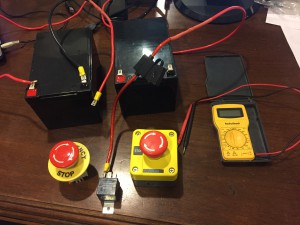
E-Stop buttons with relay and fuse link
Since both buttons are rated for only ten amps, and the circuit potentially can pull twenty-nine amps, I also installed a forty-amp relay. So the e-stop buttons control the relay, and not the actual circuit. The relay does the heavy lifting for handling the higher amperage.
Most relays that are readily available are for automotive use and are rated for twelve volts. My circuit has two twelve volt batteries in series, so will be pushing twenty-four volts. I wasn’t sure that I could tap into just twelve of the twenty-four volts to power my relay (turns out that I can, I now know), and didn’t know what problems I might have if I tried to power a twelve volt relay with twenty-four volts. But I was able to find a relay that’s rated for twenty-four volts, so it wasn’t an issue.
Or at least, that’s what I assumed. It turns out that, when I was testing the circuit with just one battery installed (running twelve volts), there wasn’t enough juice to power the relay. So I couldn’t even get the circuit to close with just twelve volts. So now I have to run the circuit at the full twenty-four volts, or not at all.
Circuit with E-Stop buttons
Here’s what the wiring looks like with the E-Stop buttons installed. Notice bundle of wires that are routed up the firewall so they can sit inside the steel drum. I’ll eventually drill the hole to mount the button through the firewall, once I get the firewall controls laid out, and attach the relay to the firewall so it doesn’t hang down.
The smokestack is one of those components I’ve been putting off, mainly because I didn’t know how I was going to construct it and attach it. The original plans call for a six inch metal duct – the same duct work that’s in the HVAC system of your house. Attached to the top of the duct is a milk strainer.
I don’t know what a milk strainer is, and I’m sure I’ve never seen one. A quick Google search shows some strainers used in the dairy industry. But they’re very expensive, and I couldn’t even find one that was radially symmetrical. But I did find a duct reducer as part of the Google search.
The duct reducer is just a specialized fitting for HVAC ductwork that connects a larger diameter duct to a smaller diameter one. I ordered one from an online source that would attach a ten inch duct to a six inch duct.
The plans called for attaching the duct to the steel drum by cutting some compound curves in a couple of wood blocks. After cutting the blocks twice, I realized I could never get it right. My solution was to cut a pair of half-round shapes from scrap two-by-four blocks so that they fit inside the six-inch duct. I glued these in place using clear silicon at the bottom of the duct piece. Helpful tip: every handyman’s toolbox should include a tube of clear silicone and a roll of duct tape.
Then I inserted four long screws into the blocks of wood and drilled holes in the barrel for the screws to attach. The last step was to install some automotive rubber weatherstripping around the bottom of the duct to create a cleaner look.


