Category Archives: Tweaking and Debugging

Putting It All Together

I’m close to having the first phase of this train-building exercise completed.  Here is a video of the (mostly) completed engine running on the track:

I’m in the debugging phase now.  I have a mostly complete engine and set of tracks.  I expect to find a number of problems that will need addressing and tweaking, but I’ll work through those as they become apparent.

Staying on Track

The first set of problems that became immediately apparent have to do with keeping the train on track – literally.  There are some locations on the track where the engine jumps the track on a consistent basis.

I’m tuning the track so the engine can run in a clockwise direction, mainly to avoid having to climb a rather steep section of the track if it were going in the other direction.  What I’ve noticed is that the tendency of the engine to jump the track is dependent on that front left wheel.

As the engine approaches the curved section of the track, the front left wheel is forced to turn when the wheel flange contacts the inside of the rail.  Since my track is not completely level, there are some sections where there is more weight on the front wheels than there is in other sections.  If there’s not enough weight on the wheel, it can easily climb the rail and go off track.

I suppose one solution would be to replace the flange on that wheel with a flange that’s larger in diameter.  But I’d have to completely replace the wheel and find a v-pulley with a larger flange.  Another solution might be to add weight to the engine on the front to help keep the wheel from climbing.

With a little experimentation, I found that I could adjust the track by shimming sections to help keep a consistent weight at all sections of the track.  That seems to work, although I’ll learn more as time goes on.

Chain Jumping

Another problem is that the drive chain has a tendency to jump off the sprocket.  This could be caused by incorrect chain tension or by the drive and slave sprockets not being properly aligned.  It also can be caused if the drive sprocket is too small.
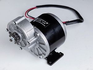
350 Watt Motor with nine tooth drive gear

The 350 Watt drive motors I used have built-in gear reductions.  I picked these motors in part because I needed the motor shaft to turn at a certain speed to drive the engine.  The motors came with a chain sprocket already attached.  Unfortunately, the attached sprocket has only nine teeth.  This doesn’t provide enough contact with the chain to keep the chain from jumping the sprocket.

I found some replacement sprockets that match the chain size that contain thirteen teeth instead of nine.  I’ve ordered these sprockets.  When they arrive, I’ll swap out the sprockets (maybe having to add links to the chains to make them longer).  I fully expect that this will solve the jumping problem.  More on this when I’ve made the changes.

Update

The thirteen-tooth sprockets finally arrived.  I removed the nine-tooth sprockets from the motors and replaced them with the thirteen-tooth sprockets.  The sprockets fit just fine, and the change in the chain path did not cause any interference with the chassis.  That was one of my concerns – that by changing the chain path it would interfere with the chassis.  If that had happened, then I’d have to reposition the motors somehow to restore the required clearances.

As expected, however, the existing chains now were too short to accommodate the larger sprockets.  I had to add a few links to the chains to make them long enough.  Fortunately, I had anticipated this and had ordered a few extra links when I ordered the sprockets, so that wasn’t a problem.

On the first test of the upgraded drive train one of the chains immediately came off the drive sprocket while the neighbors were watching.  But all it required to fix was an adjustment of the motor to get the alignment and chain tension correct.  After that, it seemed to work fine.

In the two weeks that followed, there have been four different children who have logged maybe fifty laps around the track with almost no problems.  The only two problems were when a small limb fell from a tree onto the track near a track joint.  The pilot wheel caught the limb and climbed over the rail, causing it to come off track.  Another lesson learned: always inspect the track before every run.

The other problem was when I opened the train house doors, but didn’t latch them in the open position.  When the train came through the back door (under remote control and out of line of sight), it caught the edge of the partially opened door with a resounding thunk.  ‘Nother lesson learned.

Next Steps: Add amplified speakers and electronics to the on-board computer to play sound files to create the chug-chug sound and maybe a train steam engine whistle.

Bells and Whistles

Ok.  So it’s really more like “Chugs and Whistles”, but this title sounds better.

I’d like to add sound to play through some on-board speakers to give the engine the “chug-chug” sound.  And maybe add a sound file for a steam whistle.

I found some sound files on the internet that I think would make a nice addition.  Here’s the sound file for the “chug-chug” sound:

And here’s a couple of the steam-engine whistle sounds I’d like to use:

I’ll need to figure out how to integrate these into the on-board computer to play these sounds through some speakers.

The first step is to make the sound files available to the computer.  Since I already have an Arduino computer installed to drive the motors and handle the remote control, I should be able to have it handle the sound as well.  But it’s not as easy as you might think.

To store the sound file I’ll need to install an SD card and add the circuitry and programming to read a computer file.  Then, I’ll need some sort of DAC (Digital to Analog Converter) to turn the digital sound file into an analog signal that can drive a speaker.  And I’ll need to amplify the speaker signal, since the Arduino emits only about fifty milliamps of power – not nearly enough to power a speaker.

Adafruit Music Maker card

Since the circuitry is so complex, I looked for an alternative where I could buy some sort of component that already has this built in.  After some searching, I settled on the Adafruit “Music Maker” MP3 Shield for Arduino w/3W Stereo Amp.  This component includes an SD card slot, the DAC, and has a built-in amplifier.

The card requires some assembly and soldering, but is made to fit neatly with the Arduino computer.  Here’s the Arduino computer and the components of the music card:

Music card with computer

After assembling the Adafruit card, I attached it to the Arduino computer to see how it performs.  And immediately realized I have a problem.

The Arduino computer card has a number of ports for attaching wires to control motors or to read sensors.  But, while the Adafruit Music Maker card fits the Arduino computer like a hand in a glove, it uses all of the Arduino ports for its interface.  The reason this is a problem is that I’m already using several of the ports to read sensors for the throttle and remote control unit, as well as for sending signals to drive the motor.

So to solve this problem I just bought a second Arduino computer to dedicate to the sound module.  After getting it installed, I was able to read the sound files for the choo-choo and whistle sounds and play it through the speakers.

Adding a separate Arduino computer to dedicate to the sound function raised another problem.  I want the choo-choo sound to begin when the train starts moving, and to stop when the train stops.  So I somehow need to have the main computer controlling the throttle to signal the second computer controlling the playing of the sound.  So I tied the two computers together in a Master-Slave configuration.  Now, when the throttle advances beyond zero, it signals the sound computer to wake up and play its sound.

The speakers came from some old computer speakers I had laying around.  I took the speakers out of the case and wired them into my circuits, using the Adafruit amplifier to get the maximum volume of sound.

Unfortunately, the sound still wasn’t very loud.  It gets drowned out by the noise of the whine of the electric motors and drive train.

So then I purchased a set of car speakers and an amplifier used in car sound systems to further boost the volume.  My computer speakers are rated at five watts, while the car speakers are rated 35 watts RMS with a 140 watt peak.  And the amplifier includes a volume control knob that should provide some adjustment as required.  Here’s what the amplifier and speakers look like:

Amplifier and speakers

So that’s where the sound enhancement stands at the moment.  Next steps are to install the new speakers and amplifier and see (hear) what happens!

Crossing Signal

This is what a “real” crossing signal looks like

I built a crossing ramp to let me get my lawn tractor across the tracks to the infield.  As long as I have a crossing, I decided I need a crossing signal.  What I’d really like is a set of the twin red lights that blink in an alternating pattern when the train comes, just like a real railroad.  Since I can’t find anything suitable anywhere (not even eBay or Amazon), I’ll have to build my own.

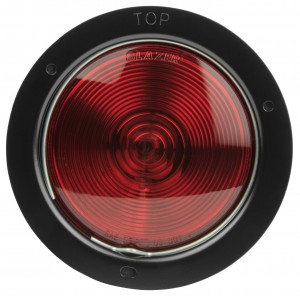
The first step was figuring out how to make this happen, and determine what parts I needed.  The red lights were pretty easy.  Auto parts stores have generic red lights that run on twelve volts DC that can be used for my lights.  I found quite a selection on Amazon.  But about nine out of ten of the lights sold today are the LED lights.  I wanted the older style incandescent lights just to make it look more authentic.  The LED lights are instant on and instant off, while the incandescent lights glow in and glow out.  These are the lights I ordered:

12v generic tail light for crossing signal

The next step was to make the black round background with the black visor.  I had some aluminum flashing left over from the train house.  So I cut the round background with a center hole sized to the housing for the tail lights.  Then I cut a piece for the visor.  Everything was attached to some scrap exterior plywood left over from the train house floor.  A coat of flat black paint (I used barbecue grill paint that I had left over), and the lighting housing was ready to go.

To power the lights I purchased (again on Amazon) an exterior weather box to house the components.  In order to have the lights come on when the train approaches and to blink in the proper pattern, I needed to build another computer circuit.  I purchased yet another (my third) Arduino computer to handle the lighting controls.

I needed to somehow have the computer sense when the engine was in close proximity so it would know to start the lighting sequence.  There are InfraRed (IR) sensors available for use with Arduino computers.  But there were two problems: first, IR sensors are for measuring in inches, while I needed to get a reading when the engine was several feet away.  Also, in an outdoor application, I was afraid that the ambient sunlight would include the same spectrum of IR light that the sensor was trying to read, so it would be washed out.

UltraSonic Distance Sensor

The alternative was to use an ultra-sound sensor.  I found this HC-SR04 Ultrasonic Sensor on Amazon.  It emits ultra-sonic sound waves from one of the ports, and reads the reflection from the other port.  Based on the time interval from send to receive, it’s easy to calculate the distance.  So I wired this sensor into my Arduino computer.

Crossing Signal Relay

Next step was to make the lights blink in an alternating pattern.  The Arduino doesn’t emit enough power to run the lights. so I needed to add a couple of relays.  The computer can trigger the relay, which acts as a switch to turn a separate and more powerful circuit on and off to work the lights.  I was going to use an automobile relay similar to the one I used on the engine, but then found that there are relays made for Arduino projects that are easily incorporated into Arduino circuts.  This is the component I used.  Note that it has four relays, while I need only two (one per light).  I thought it might be prudent to have some spares, as I’ve fried a few of these components while trying to get them to work.

I programmed the Arduino computer so that it’s constantly watching for something on the track within a few feet.  Once it senses that it’s there, it wakes up the relays and alternately flashes the lights for a few cycles.  Then it goes back to sleep.

Crossing Signal Circuitry

I put all of this, including a small twelve volt battery, into the weather housing and mounted it on the crossing sign pole.  I cut two small holes in the side of the box for the sensor to look through.  This makes the sensor exposed to the weather, so I don’t know how long it will last before I have to replace it.  We’ll see over time.  Then I plugged the Arduino into my laptop computer to calibrate the settings and hoped that it would work.

Crossing Signal Calibration

Once I had everything working, I closed up the box and ran the live test.  Here is a video of everything in service:

If I can find the right type of bell, I’d like to add it to the pole and get the ding ding sound while the lights flash.  But most of the bells I’ve found so far are like the school bells that ring continuously.  I need one that runs on twelve volts DC that can ring with individual dings.  And it needs to be weather resistant.  I’ll keep looking – maybe I can get that added one day.

Update #1:

I’ve researched bells for my application.  It looks like the closest thing readily available would be either a school bell or a fire bell.  But these bells ring continuously.  I need a bell that I can have ding just once.  Then I can control the dinging with my Arduino computer.

I posted an inquiry on a hobby forum and received a response from across the country in which someone offered a bell salvaged from an old Kodak x-ray film developing machine.  The bell was powered by 120 VAC, but should be able to be modified to run on a 12 VDC by removing some of the wire windings in the armature.  I’m waiting on the arrival of the bell.  Then we’ll see if it can be modified to run in my crossing signal.  More when it develops…