I don’t have any plans or guidelines for the motor controller, so I’m on my own. Here’s the issue: the two 350W DC motors will be powered by a pair of twelve volt wheelchair batteries wired in series, which will provide twenty-four volts of power. If the power is controlled by an on-off switch, then turning the power on would provide the full flow of current instantaneously. The motors would go from zero to full speed immediately, causing the engine to jerk as it attempts to go immediately from zero to full speed.
In addition, there would be no provisions for speed control. With this configuration, it’s either no power or full power, with no intermediate speeds.
To provide for a gradual and smooth ramp-up of power and speed, we need some way to make the motors run at a variable speed, sort of like a variable speed drill. In researching this problem on the World Wide Web (i.e., “Google”), I’ve learned quite a bit about how to make this happen. While there are several approaches, the consensus approach is to use an H-Bridge and a digital controller.
The H-Bridge is a device that uses Pulse Width Modulation (PWM) to control a motor. Think of a stream of current flowing at twenty-four volts. Now divide that stream into pulses so that there are thousands of pulses each second. For each micro-pulse, imagine that you can somehow modulate the pulse so that the voltage flows for just a percentage of the pulse. For example, at 20% there would be voltage flowing for 20% of the pulse, and no voltage flowing for the remaining 80%. The high frequency of the pulses would have a smoothing effect, such that when the motor sees the current, it only sees a smooth flow of 20% of the power flowing. So the twenty-four volts would look like 4.8V to the motor. That’s essentially what the H-Bridge does.
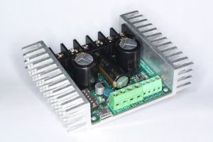
After some more research and reviews, I selected for the H-Bridge a component called Sabertooth sold by DimensionEngineering.com. This device lets you hook the battery wired into its terminals, and the motor leads into other terminals. It also lets you wire a signal wire into it to control the voltage. So to run the motors at 10% capacity, you can provide the signal wire the appropriate value and it routes 10% of the incoming power to the motors.
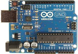
The next question is how to provide the signal. I’m using a programmable microcontroller board called the Arduino Uno. This board allows you to develop your own computer program that you can download to the board. It also allows you to (among other things) attach various sensors that it can monitor and respond to. So you can attach a potentiometer, for example, that you can use as a throttle. The potentiometer allows you to dial in a variable speed value that the board can sense. Think of the volume control knob on an old radio. The more you turn it, the louder the volume.
By sending the adjusted values of the potentiometer to the controller board, the board can then determine what speed the motors should be running and send the appropriate signal to the Sabertooth board. That’s basically how my motor control circuit will work.
By developing my own computer control software, I can have it make one wheel turn faster in a curve than the other. The custom control circuitry opens up a number of other possibilities for enhancements down the road (track?), including adding a sound module and speaker to make steam engine sounds or train whistle sounds, control lights, or other things I haven’t even thought of yet.

It also lets me integrate a Radio Control (RC) capability. I’d like to be able to control the train either with an on-board speed control or with an RC transmitter so I can control it remotely for testing and maintenance. When small children are on board, it also will let me take control remotely if they’re about to get into trouble. I’m using the FlySky FS-CT6B RC controller.
Here’s my first microcontrol circuit board:

The unit on the right with the cooling fins is the Sabertooth motor controller. The middle unit is a PCB board with a potentiometer soldered in to set the speed, and the unit on the right is the Arduino programmable microcontroller. The little black thing on the bottom is a RC receiver that listens for the Radio Controller commands. The rat’s nest of wires ties it all together. I’m hoping that Homeland Security doesn’t take an interest in this!
Update:
Eventually I’ll need to figure out where on the engine to mount the batteries and electronics and get the wiring in place. For now, it occurs to me that I’ll need some sort of Kill Switch as a safety device. If something goes wrong that I didn’t foresee, there needs to be a big red STOP button that the operator can slap to shut the whole thing down. It can also double as a power disconnect to prevent any possible battery drain.
Update on the Update:
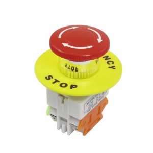
I’ve looked into the big red STOP button. The proper term is “E-Stop” (for Emergency Stop). All of the buttons I’ve found on the World Wide Web (at least that are affordable) are rated at ten amps. Since I’m going to run twenty-four volts into a pair of 350W motors, I’ll potentially be drawing around twenty-nine amps of power. So it’s probably not a good idea to route all this power through a ten amp button.
The alternative is to do what they do in automobiles for horns and lights that draw more power than a typical switch can accommodate: build a relay circuit.
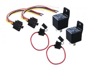
I can get an automotive relay rated at thirty or forty amps and have the ten amp E-Stop button control the relay. The relay can control the circuit that handles the higher load. It’s a little more complexity than I was hoping for, but it is what it is.
While I was thinking about this problem it also occurred to me that I probably need to put some sort of line fuse in while I’m building the circuit. Again, if something unforeseen goes wrong, I’d rather burn out a one dollar fuse than a hundred-plus dollar control circuit.