All posts by rwreagan

Kill Switch

Emergency Stop button from Amazon

The kill button finally arrived from China via Amazon.com.  It’s a big red button on a yellow faceplate that can mount against the firewall.  In the meantime, a friend gave me a surplus Emergency Stop button that he had on hand.

The button my friend gave me is a surface mount instead of a flush mount.  I’d rather have the flush mount in the cab so that it doesn’t intrude quite as much.  Fortunately, the other button is a flush mount, so that’s the one that I’ll install in the firewall.

Since I now have two Emergency Stop buttons, I can wire them in series so that either button will interrupt the flow of power to the motors.  I’ll put one in the cab for the operator, and the second  “under the hood” next to the batteries.  That way I can more conveniently disengage the circuit when charging the batteries.

E-Stop buttons with relay and fuse link

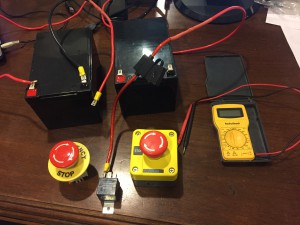
Since both buttons are rated for only ten amps, and the circuit potentially can pull twenty-nine amps, I also installed a forty-amp relay.  So the e-stop buttons control the relay, and not the actual circuit.  The relay does the heavy lifting for handling the higher amperage.

Most relays that are readily available are for automotive use and are rated for twelve volts.  My circuit has two twelve volt batteries in series, so will be pushing twenty-four volts.  I wasn’t sure that I could tap into just twelve of the twenty-four volts to power my relay (turns out that I can, I now know), and didn’t know what problems I might have if I tried to power a twelve volt relay with twenty-four volts.  But I was able to find a relay that’s rated for twenty-four volts, so it wasn’t an issue.

Or at least, that’s what I assumed.  It turns out that, when I was testing the circuit with just one battery installed (running twelve volts), there wasn’t enough juice to power the relay.  So I couldn’t even get the circuit to close with just twelve volts.  So now I have to run the circuit at the full twenty-four volts, or not at all.

Circuit with E-Stop buttons

Here’s what the wiring looks like with the E-Stop buttons installed.  Notice bundle of wires that are routed up the firewall so they can sit inside the steel drum.  I’ll eventually drill the hole to mount the button through the firewall, once I get the firewall controls laid out, and attach the relay to the firewall so it doesn’t hang down.

Smokestack

The smokestack is one of those components I’ve been putting off, mainly because I didn’t know how I was going to construct it and attach it.  The original plans call for a six inch metal duct – the same duct work that’s in the HVAC system of your house.  Attached to the top of the duct is a milk strainer.

I don’t know what a milk strainer is, and I’m sure I’ve never seen one.  A quick Google search shows some strainers used in the dairy industry.  But they’re very expensive, and I couldn’t even find one that was radially symmetrical.  But I did find a duct reducer as part of the Google search.

The duct reducer is just a specialized fitting for HVAC ductwork that connects a larger diameter duct to a smaller diameter one.  I ordered one from an online source that would attach a ten inch duct to a six inch duct.

The plans called for attaching the duct to the steel drum by cutting some compound curves in a couple of wood blocks.  After cutting the blocks twice, I realized I could never get it right.  My solution was to cut a pair of half-round shapes from scrap two-by-four blocks so that they fit inside the six-inch duct.  I glued these in place using clear silicon at the bottom of the duct piece.  Helpful tip: every handyman’s toolbox should include a tube of clear silicone and a roll of duct tape.

Then I inserted four long screws into the blocks of wood and drilled holes in the barrel for the screws to attach.  The last step was to install some automotive rubber weatherstripping around the bottom of the duct to create a cleaner look.

Smokestack

Here’s what it looks like:

Hill Climbing Tests

The area I have for the track comprises a racetrack oval pattern with about 275 feet of track.  Since the track route isn’t level, I need to know if the engine will have the power and traction to climb a slight grade.  If not, then I’ll have to figure out something else for the track.  So design and construction of the track is waiting on the results of a hill-climbing test.

I built four sections of straight track using eight foot lengths of lumber to use as a test bed (I’ll reuse these sections in the final version of the track, as well).  I put the track sections on a relatively level portion of the backyard, set the engine on it, and had the first outdoor run just as a test.  I controlled the engine with the remote control and was able to make it go forward, backward, speed, slow, and stop.

Now that I know the engine can power itself and stay on track (pun intended – did you see what I did there?), the next test was to see if it could climb a hill.  I repositioned the track on the steepest slope in the yard, which measured at a 15% grade.  That’s pretty steep for a train track.  If it can handle this slope, then it will be able to handle any slope in the eventual track bed.

The first test of the engine trying to climb the slope had the engine sliding backward down the hill, even while the wheels were spinning trying to power it forward.  So the limiting factor was traction, not power.

I added my weight to the engine by standing in the cab, hoping that the extra weight would improve the traction enough to move it forward.  Here’s the video of that test:

So now I know the engine can handle the steepest slope that will be in the eventual track route.

Siderod Attachment

Side rod (or Connecting rod)

The side rod (or connecting rod) of a real steam engine connects the piston to the engine’s drive wheels.  It works like the connecting rods of a standard gasoline engine that connects the piston to the crankshaft.  The steam pressure pushes the piston, which is connected to the side rod.  The other end of the side rod is attached to the drive wheel and causes it to rotate.

Since this engine is driven by electric DC motors with a chain drive, the side rods are entirely superfluous and decorative.  But it makes a nice visual to help complete the effect.

FRONT END OF SIDE ROD

For the piston rod, I have a half-inch steel rod that sits in five-eights inch diameter holes drilled into the wooden end caps of the cylinder.  The rod can slide freely.  I threaded the rear end of the rod with a die cutter so that I can attach some sort of fitting to attach to the side rod.  My original plan was to fabricate a bracket by bending and drilling steel bar stock and attach to the piston rod with nuts.  But when browsing the hardware store for something to use I found a galvanized pipe fitting Tee that I thought I might be able to use.

The inside of the pipe fitting was already threaded.  But it turns out that the thread pitch of the pipe fitting was not the same as the thread of the steel rod that I cut.  Not a problem – I just re-threaded the pipe fitting to match my steel rod with a thread cutting die.  I screwed the rod into the fitting and locked it with a nut.

Side Rod Wrist Pin

The fittings were also threaded on the sides, so I drilled them out.  I found some clevis pins at the hardware store of the proper diameter and length and used those to create the wrist pins that attach the side rod to the piston rod.  Here is a picture of the final assembly of the front end of the side rod.  Note that the pipe fitting is just a little too wide for the side rod, which was cut weeks ago.  I added a second layer of bar stock to the back side of the side rod to use as a spacer to prevent binding.

BACK END OF SIDE ROD

The back end of the side rod attaches to the drive wheel.  The drive wheel has a half-inch steel bolt protruding from the side of the wheel, to which the rod is attached.  I drilled a hole in the rod and inserted a bronze bushing that I lubricated with a little axle grease.

A real steam engine also has additional rods that are used to control the valves that allow steam into the cylinders at the proper time.  The control of these valves is determined by the position of the wheel during the rotation cycle.  So the wheel typically will have additional linkages for this purpose.  These linkages are included in this design and create another nice visual effect.

Drive Wheel Linkages

The fittings for the linkages were fabricated from steel bar stock that I cut with a jigsaw.  Then I drilled and ground the pieces to get the desired shapes.  The fabricated pieces are attached to the steel bolt with locking nuts.  The other end includes a bolt to hold the actuating rod that gets pushed and pulled during the wheel rotation.  You can see a picture of the assembly here.

Here’s what the final side rod assembly looks like in operation:

General Approach to Building the Track

Since I’ve never built a train track, I’m sure that I’ll learn more than I’ll ever wanted to know about train tracks by the time I have it completed.  I’m also sure that I’ll eventually look back and realize that I would have done some things differently once I’ve gone through the process.

That said, I plan to research as much as I can to reduce the risk that I’ll have to scrap major pieces of work after the fact because I didn’t have the knowledge to do it right the first time.

So, from my reading, here’s some things to be considered when I design and build the track:

  • The width between the rails is critical.  If the distance between the wheel flanges is 14.5″, then there needs to be another quarter inch added for the distance between the rails so the wheels don’t bind.
  • The width between the rails in the curved sections needs to be about one eighth of an inch larger to keep the wheels from climbing the rails and derailing.
  • The curved sections can’t be too tight.  The degree of curve is expressed as the distance of the radius that would scribe the curve.  From reading, it seems that the tightest curve that the train will be able to handle is about a thirty foot radius.  If you think about the geometry, the minimum radius of the curve would have to be increased if the wheelbase of the engine increases or as the track width increases.  I’m going with the thirty-foot radius and hoping it works out.
  • The grade of the track can’t be too steep.  It seems from reading that a three or four percent grade is pretty much the maximum that a train should encounter.  Because of the slope on the property where the track will go, I may have as much as a twelve or fourteen percent grade.  Based on the hill-climbing tests I’ve already conducted, I know the motors have enough power to handle a fifteen percent grade, assuming I can get enough traction to keep the wheels from slipping.

So my general approach to building the track will be to create track sections that can be attached to each other on the track bed.  The curve sections will need to reflect a thirty foot radius, so I’ll build some sort of template for those.  In addition, I need to ensure that the distance between the two rails is consistent.  So I’ll need some sort of template to ensure that the distance between the two rails doesn’t vary as I assemble the track sections.

Once I get some curve sections of track completed, I’ll want to run a test to make sure the engine can handle the curve without derailing.  Assuming that test works well, then I can use this approach for the remainder of the curve sections.

I’ll also need to figure out how I want to set the track on the ground.  The simplest way would be to just lay the sections on the ground.  There may be several problems with this approach, however.  The ground is uneven, so the track would be uneven as well.  If the track tilts to the side, then the engine will also tilt on that section of the track.  Too much tilt and it may fall over.  That would be a train wreck.  Not good.  Also, the grass and weeds will grow between the cross-ties and will be a nuisance to control.

The best approach would be to set the track on a bed of ballast (gravel) to give it the best support and enable me to make leveling adjustments.  I don’t want to have to deal with removing tons of gravel at some point in the future, so I’ll start with no gravel and see how it goes.  Maybe later, if necessary…

So, let’s get started!

Making Straight Track

Rails

Track construction can be divided into making the rails and making the cross-ties.  The rails are made by ripping a 5/4″ decking board into three strips that are equal in width.  Deckboard is used, as it is easy to work with, readily available, and comes pressure-treated.

Cutting the deckboard into strips leaves two rails that have the rounded edges, and a center strip that has square edges.  I used a router with a quarter-inch rounding bit to round the edges of the center strip.  This way, I can get three rails from one deckboard.

Cross Ties

The cross ties are made from pressure-treated 2x4s that are cut into two-foot lengths.  To ensure that the rails keep the proper distance between them and are firmly anchored to the cross ties, I cut grooves into the cross ties to hold the rails.  Since the 5/4″ deckboards are actually one inch in thickness, I needed grooves that were one inch wide and that were spaced the proper distance apart.

My first thought about cutting the groves was to put a dado blade on the table saw.  But a little research showed that there are no dado blades for a ten-inch table saw that are one inch wide.  This would have necessitated at least two passes per groove, and it would have been difficult to ensure that the groves maintained the proper widths and distances between each other.

My first attempt at actually cutting the grooves was to just make multiple passes over the table saw blade with each pass cutting just the width of the saw kerf.  I made enough cross ties to construct an eight-foot section of straight track.  But the process was labor-intensive and prone to error.  Not a good solution for cutting hundreds of ties.

I abandoned the approach of using a table saw for cutting the grooves in favor of using a router.  I found a router bit that cuts a one-inch wide groove with a single pass.  This approach looked much more promising.

Cutting grooves in cross ties

What I finally ended up doing was to attach several ties with bar clamps so I could cut all of them with a single pass of the router.  I also cut a piece of plywood with a width such that it could be used as a router guide and ensure that the grooves for each side of the tie maintained the proper spacing.  Here’s what the setup looked like:

Straight Track

Using this approach to making straight sections of rail, I constructed several sections and connected them so I could run an engine test.  The test was just to make sure that the engine would track along the rails without jumping the tracks.

Making Curved Track

There are two types of track sections: straight and curved.  While the straight sections are straight-forward (pardon the pun), the curved sections can be a challenge.

Plan A

Track Curve Template

My first attempt to making a section of curved track was to lay out a template on the garage floor and use this template to guide the positioning of the cross ties and rails.  I scribed an eight-foot long arc with a thirty-foot radius on the garage floor and marked it with tape.  This is what it looked like:

Then I positioned the grooved cross-ties on the guides and tried to fit the rails in the grooves, bending them as necessary.  I’d get one rail in one of the grooves, and something would pop out of another tie at the other end of the section.  I might could have been successful with this approach if I had two dozen hands and the strength of ten men.  So I quickly abandoned this and formulated Plan B.

Plan B

My second approach was to create a jig that would position the rails in a curved configuration and hold them so I could attach the ties.  I fastened a set of cross-ties to a piece of plywood so that the rails would scribe the thirty-foot radius.  By forcing the rails into the grooves, I could then have them held in place while I attached each of the cross-ties using deck screws.  This worked much better, as you can see here.

Each eight-foot section of curved track covers about fifteen degrees of curvature, so it takes twenty-four sections to make the complete 360 degree circle.  Using this template, I created all twenty-four sections.  Then I created some more straight track sections to make up the gap.  Next step was to see if the engine would follow the track without derailing.

Running Engine Test of Curved Track

Curved Track

I laid out the curved sections on the ground and connected the sections. I also drilled some half-inch holes in some of the ties and drove a length of rebar through the holes into the ground to keep the track from shifting out of position.

Weed control

Since it would be a constant battle to keep the grass and weeds from taking over the track, I killed the grass along the track bed and rolled out some grass mat to prevent the grass from growing back.  I’m hoping this will be enough to keep the grass and weeds from covering the track.  Later I’ll cover the black cloth with either gravel or maybe some mulch to give the appearance of track ballast and to hide the mat.

When I ran a test of the engine to see if it would follow the track without derailing, here’s how the test went:

Engine House Design

I need to build an engine house to have a place to store the train engine and keep it out of the weather.  Most trains that I’ve seen have a separate switch spur that allows the engine to roll into the house.  For now, I’m going to take a simpler approach and just build the engine house on top of the main loop of the track.  This way, I don’t have to add more track and build a switch.  Of course, this means that the engine house will need doors at both the track entrance and exit to allow the train to roll through.

I looked on Google at a number of pictures of engine houses, trying to get a flavor of what the architecture might look like.  Unfortunately, most of the pictures of engine houses are of structures that are rather plain and utilitarian.  So there doesn’t seem to be a lot of latitude in how to design the structure to look “railroadish”.

I did get a few ideas, though.  By incorporating these into a design, this is sort of what I have in mind for my engine house:

Engine House Design

I’m going to make it bigger than necessary for housing the engine.  That way I’ll have some storage capacity for parts and spares related to maintaining the railroad.

I initially was planning on a shed that was ten by twelve feet.  But the proximity of the track to some trees that I’m unwilling to cut means that the largest I can make it will be ten by ten.

The shed floor can’t span the entire width of the house, as the track needs to be exposed inside the house.  So to maximize storage capacity, I’ll have the track running along one side of the house to leave as much area as possible for the floor in the remainder of the shed.  That’s why you see the track going into the side of the house instead of into the middle.

To preserve a look of symmetry, I’ll have a real door over the track entrance and exit, and a faux door on the other side of the structure that won’t be functional.  And to keep it from looking too plain, I plan to have a “chicken coop” along the roof ridge.  I’m sure there’s an architectural term for this, but I don’t know what it is.  But I did see this feature in a number of the pictures of engine houses, so “I’ll have one of what she’s having!”.